Software / Firmware
## Design considerations
The main directive behind most of the decisions we took for this project was to achieve “full modularity” in our game. We describe “full modularity” as the ability to connect any individual module (no matter how complex it is) to the main module using the same input and achieve the same game core mechanics (solve all of the modules to defuse the bomb, if there is an error in a solution, add a strike to the counter).
We identified early on in the project that in order to make a game that allows for “full modularity”, the individual modules must be kept as independent as possible from the main module. We achieved this by keeping the communication between the main module and the individual modules to the bare minimum for proper functionality of the integrated design and gameplay experience.
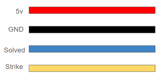
This can be seen with our reasoning for developing our standard molex connectors that connect our individual modules to the main module. As a remainder, our standard connector has only 4 lanes, the first two are used for connection to ground and power (enabling the basic functionality of the module) and the other two are used to transmit two types of data to the main module: If the module generated a STRIKE, and if the module has been SOLVED (enabling our desired game experience).
These decisions (motivated by our objective of achieving “full modularity”) affected our software implementations in a couple of ways:
- The minimal communication design means that the only “standard” considerations that we need to take care of when programming an individual module are the handling of strikes and module solutions.
- As a result, almost all of the design decisions that need to be taken to develop a module are up to the module developer to take however they see appropriate to do so.
This will become evident in the individual sections regarding our implementation of each of the modules.
Programming Platform
All the code for the microcontrollers was written in C++ using platform.io. We chose this platform as it allows us to have a better organization structure. All platform.io projects have a configuration file that helps us develop each module with ease. Also, platform.io provides the same functionality that the Arduino IDE has in Visual Studio Code.
Notes on platform.io projects:
There are a couple of differences when developing projects in platform.io as opposed to the Arduino IDE. These must be taken into consideration when developing a program.
-
Platform.io can be used to program multiple microcontrollers, to allow a program to be compatible with Arduino’s built-in functions, the line
#include <Arduino.h>must be included. This line is added by default when creating a platform.io project. -
Functions need to be declared before void setup and void loop. Code developed using the Arduino IDE might need some slight modifications to adhere to this requirement.
-
The handling of libraries is different for platform.io projects compared to programs developed using the Arduino IDE. To use the default arduino libraries installed through the Arduino IDE, we need to add the following line of code at the end of the configuration file of the platform.io project:
lib_extra_dirs = ~/Location of the Arduino folder/libraries
Standard Configurations Among Modules
As we mentioned before, the “standard” considerations that must be implemented in the programming for every individual module are only related to the handling of game strikes and module solutions. From a gameplay perspective, all modules should be able to perform two basic tasks:
-
Send a temporary strike signal when the player makes a mistake while trying to solve the module.
-
Once a module has been solved, continuously send a solved signal (a solved module should stay in its solved state until the end of the playthrough).
In the code, we implemented these tasks as follows:
-
Once a strike occurs, the microcontroller sets the designated STRIKE pin HIGH for at least 1000 milliseconds and then it sets that pin LOW to avoid sending more than one strike per error.
-
Once the module is solved, the microcontroller sets the designated SOLVED pin HIGH and keeps it in that state for the rest of the game.
A basic implementation of this standard game loop is the following:
// Import the arduino library to use in platform.io
#include <Arduino.h>


// Set the communication pins
#define STRIKE  3
#define SOLVED  4


bool solved = false;  // Keeps track of the game state


// Strike and solved examples. Used only for demonstration purposes
bool strike;
bool solution;


void setup() {
  pinMode(STRIKE, OUTPUT);
  pinMode(SOLVED, OUTPUT);
}

void loop() {
  while (!solved) {
    // Continue looping through the game.


    if (strike) {
      // If a strike happens, send a strike signal for 1 second
      digitalWrite(STRIKE, HIGH);
      delay(1000);
      digitalWrite(SOLVED, LOW);
    }


    if (solution) {
      // If the solution of the module has been found, break the loop
      solved = true;
    }
  }


  // Once the module is solved, send a solved signal continuously.
  digitalWrite(SOLVED, HIGH);
}
We used this basic implementation in 4 out of the 5 modules we developed (morse code, keypad, memory and button); however, this is not the only way to implement a loop that satisfies the basic tasks that are required for any given module as we will explore in the implementation of the wires module. For this reason, we opted to avoid setting this example as the “standard” implementation of a module, leaving the developer with the freedom to implement the loop as it fits best for the particular game loop of the module. As long as it accomplishes the two tasks required for all modules, we consider the implementation “appropriate” for the game. This decision also allows the developer to better accomplish another one of our objectives: optimize the gameplay experience.
From the example above, the only “standard” that must be followed for all the modules is to define specific pins to send the strike and solution communication, and set them up as outputs in the loop.
Module implementations:
With this basic understanding we will explain the implementations of the main module, and the 5 individual modules we developed.
Main Module (Timer)
Libraries:
Firmware:
This central module interfaces with our TMI1637 7 segment display, as well as some LEDs to reprisent the strikes. During code startup, we initialize a bunch of pins that reprisent the connection from one module to the central.
Software: On startup, we initialize all of our pins that connect to other modules, then some values used to calculate the current time, as well as one constant that holds a list of all the numbers we want to use on the 7 segment display
/*
 * Defining Pins for the timer
 */
const uint8_t CLK_PIN = A0;
const uint8_t DIO_PIN = 10;
const uint8_t NUM_DIGITS = 4;
const uint8_t SOLVE_PIN_BUTTON = 2;
const uint8_t SOLVE_PIN_MEMORY = 3;
const uint8_t SOLVE_PIN_WIRES = 4;
const uint8_t SOLVE_PIN_MORSE = 5;
const uint8_t SOLVE_PIN_KEYPAD = 6;
const uint8_t STRIKE_PIN = A1;
const int STRIKE_THRESH = 35;
const uint8_t STRIKE1 = 11;
const uint8_t STRIKE2 = 12;
const uint8_t STRIKE3 = 13;
const uint8_t BUZZER = 7;


/*
 * Timer initalization values
 */
const unsigned long countdownTime = 300000; // 5 minutes in milliseconds
unsigned long startTime;
unsigned long elapsedTime;
unsigned long current_time;
unsigned long last_time;

/*
 * Delay time for compensation in the electronics
 */
const uint8_t DELAY_MICROS = 100;

using TmiInterface = SimpleTmi1637Interface;
TmiInterface tmiInterface(DIO_PIN, CLK_PIN, DELAY_MICROS);
Tm1637Module<TmiInterface, NUM_DIGITS> ledModule(tmiInterface);

// LED segment patterns.
const uint8_t NUM_PATTERNS = 10;
const uint8_t PATTERNS[NUM_PATTERNS] = {
  0b00111111, // 0
  0b00000110, // 1
  0b01011011, // 2
  0b01001111, // 3
  0b01100110, // 4
  0b01101101, // 5
  0b01111101, // 6
  0b00000111, // 7
  0b01111111, // 8
  0b01101111, // 9
};

// Full Game variables
int strikes = 0;
int prev_strike_state = 0;
int current_strike_state = 0;
After this, we go on to define a few functions:
- defuse()
- explode()
- strike_led()
- check_modules()
Each of these functions are called to check the state of the game, especially when using information passed from other modules.
Finally, we enter the run loop, update the countdown timer, and check for any strikes/successes from other modules
void loop(){

  Serial.println(analogRead(STRIKE_PIN));

  check_modules();

  // Calculate elapsed time
  elapsedTime = millis() - startTime;
  unsigned long remainingTime = countdownTime - elapsedTime;

  // Display countdown value
  int minutes = remainingTime / 60000;
  int seconds = (remainingTime % 60000) / 1000;

  // Split minutes and seconds into separate digits
  int min1 = minutes / 10; // Tens place of minutes
  int min2 = minutes % 10; // Ones place of minutes
  int sec1 = seconds / 10; // Tens place of seconds
  int sec2 = seconds % 10; // Ones place of seconds

  current_time = millis();

  if (current_time >= last_time + 1000) {
    last_time = current_time;
    // Print as four separate integers
    //ledModule.setPatternAt(0, PATTERNS[0]);
    ledModule.setPatternAt(1, PATTERNS[min2]);
    ledModule.setPatternAt(2, PATTERNS[sec1]);
    ledModule.setPatternAt(3, PATTERNS[sec2]);
    //ledModule.setPatternAt(
    ledModule.setBrightness(2);
    ledModule.flush();
  }

  if(min1 + min2 + sec1 + sec2 == 0){
    explode();
  }
}
Morse Code
Libraries:
Firmware
For all of the modules that required the use of a mechanical switch to receive information, we developed a special structure called Button to prevent errors in digital readings derived from the button debounce. This structure has 3 boolean methods to identify if a button is currently being pressed, released or is being held down, and an read method that changes the state of the button (from pressed to not pressed) only once a certain amount of time has passed, avoiding conflicting readings over the span of milliseconds due to mechanical issues.
Software
During the setup of the microcontroller, a random item from the list of possible words is chosen and it is passed to an instance of the LEDMorseSender class (provided by the Arduino Morse library) in its set_message method.
In the void loop, a setup similar to the game loop example mentioned before is used to set up the module. While the module is not solved, the arduino retrieves information from the analog pin used where the potentiometer setting the “frequency” is connected to. The 10-bit analog value obtained by the arduino is converted to a number between 3500 and 3600 (range of possible frequencies in the game) and then rounded down to show the possible values in increments of 5.
freqSelectValue = analogRead(freqSelectPin);
signal_frequency = (((long)freqSelectValue * 105)/1024) + 3500;
signal_frequency = signal_frequency - (signal_frequency % 5);
This frequency value is displayed in the display. Then the arduino reads the current value of the “send” button. If its current state is pressed, it checks if the frequency currently displayed is the frequency related to the word selected during the setup; if they are the same frequency, it ends the loop by changing the value of module_solution from false to true. Otherwise, it sends a strike.
if (send_button.pressed()) {
   if (signal_frequency == solution_frequency) {
      module_solution = true;
   }
   else {
      Serial.println("********** STRIKE **************");
      digitalWrite(STRIKE, HIGH);
      delay(500);
      send_button.read();  // Read to check if the button is unpressed now
   }
}
Wires
Libraries:
- [FastLED] (https://github.com/FastLED/FastLED)
Firmware
The wires module interfaces with an LED strip to represent the wires as well as 6 switches that “cut” the wires. The firmware here basically just sets the specified number of lights to the specified color and checks for switch input.
Software
On startup, the wires are initialized by first picking a random color for any number of wires between 3 and 6.
void initWires() {
   randomSeed(analogRead(0));
   int choose_wires = random(0, 4);
   num_wires = choose_wires + 3;
   wire_index = wire_indices[choose_wires];


   int counter = 0;
   for (int i = 0; i <= wire_index; i++) {
       if (i % 4 == 0) {
           int choose_color = random(0,5);
           state_big[counter] = choose_color;
           R = colors[choose_color][0];
           G = colors[choose_color][1];
           B = colors[choose_color][2];
           counter++;
       }
       leds[i] = CRGB ( R, G, B);
       FastLED.show();
       delay(40);
   }


   // Dynamically creates a correctly sized state array
   state = new int[num_wires];
     for (int i = 0; i < num_wires; i++) {
   state[i] = state_big[i];
 }
}
The solution to the module is then calculated in another function which takes the state array and runs a bunch of checks on how many wires there are, what colors they are, etc. which will set the correct wire to cut.
if (state[4] == 4) {
           return 4;
       }
       else if (countOccurrences(state, num_wires, 0) == 1 && countOccurrences(state, num_wires, 2) > 1){
           return 1;
Lastly, the switches are simply read to check which wire the user cut. If it’s wrong, the strike line goes high for 1 second. If so, it plays a cutting animation and sets the solved line high.
Memory
Libraries
Firmware
Besides the Button structure introduced in the Morse Code module, the memory module has 4 special functions responsible to set the addressable LED strip to the desired colors.
-
initLights: Sets a delay of 3 seconds to safely turn on the LEDs, and configures the LED strip in memory (set type of LED strip, number of LEDs, brightness, etc.) in a FastLED instance. -
turn_off_lights: Sets the intensity of all the LEDs to 0, turning off the LEDs. -
display_stage: It takes a stage as a parameter and based on the values generated on setup, it sets the LEDs to light up in their corresponding colors. -
display_final_stage: Sets all of the LEDs (except for the current stage indicators) to the color white.
Software
On setup, the color of the displays for all 5 stages is randomly chosen between the 4 possible display colors, and stored in the list display_values. Then colors assigned to each of the buttons is randomized per stage by generating a random sort of the 5 lists contained in button_values which start with the 4 possible color values. The random sort is achieved using the Fisher-Yates algorithm. Finally the function find_solutions is used to (following the rules of the module) determine what are the solutions for each of the stages given the random display color and sort of button colors.
void find_solutions() {
  // STAGE 1
  if (display_values[0] == 1) {
    // If the display is 1, press the button in the second position.
    stage_solutions[0][0] = 2;
    stage_solutions[0][1] = button_values[0][2 - 1];
  }
  else if (display_values[0] == 2) {
    // If the display is 2, press the button in the second position.
    stage_solutions[0][0] = 2,
    stage_solutions[0][1] = button_values[0][2 - 1];
  }
...
These values are stored as a collection of 2-item lists (corresponding to the position and color of the button that solves each stage).
On the void loop, the input of the 4 buttons is obtained and the LEDs are set to show the current stage. Then it waits for a button to be pressed to determine the outcome of the current stage. If the button pressed is different from the solution, the module sends a strike and returns the stage counter to 1. If the button pressed and the solution are the same, it increases the stage counter until it reaches the stage 6 (all of the 5 stages have been cleared) when the game loop is finalized by setting the value of module_solution from false to true.
Keypad
Libraries
Firmware
This module includes the same Button struct that has been discussed earlier. It also has a SPI OLED Display with a SSH1106G driver which we use the adafruit display library to communicate with. All the sprites are stored in progmem.
Software
During setup, the main software component is randomly generating the solution. This is done by first picking a column:
void generateSolution() {
 int randomIndex = random(0, 6);
 int *selectedColumn = columns[randomIndex];
 Serial.print("Selected Column: ");
 int column_num = randomIndex + 1;
 Serial.println(column_num);
Then we need to pick 4 of the elements from the column, store what they are, and find the relative index of the elements within the column.
int relative_idx[4];
 selectRandomElements(selectedColumn, img_order, relative_idx, 7, 4);
 Serial.print("Image order: ");
 for (int i = 0; i<4; i++) {
   Serial.print(img_order[i]);
   Serial.print(", ");
 }
 Serial.println("");
 Serial.print("Relative index: ");
 for (int i = 0; i<4; i++) {
   Serial.print(relative_idx[i]);
   Serial.print(", ");
 }
 Serial.println("");
 getSortedIndices(relative_idx,solution,4);
}
We used a couple helper functions to do this. After the solution is generated, we display the correct images in the correct location and check for user input. If a wrong press is detected, a strike is sent. If it is solved correctly, the solved line goes high.
Button
Libraries:
Software
On setup the 6 module variables are randomly chosen: Button color (4 possible colors), button text (appears in the first screen, 4 possible words), number of batteries (up to 3 batteries), shape to show in the second screen (6 possible shapes) and the color of the light strip to the side of the button will light up (in the event it lights up).
Although the manual describes several scenarios depending on these values, all of those scenarios can be reduced to two cases; either the solution is to press the button and release it immediately, or to press the button and hold it down until a certain number in the timer from the main module.
Based on these randomly chosen conditions, the function release_immediately is used to determine if the solution is to press the button and release it immediately. The function release_immediately applies the rules from the manual and returns a boolean value that will be used during the game loop.
In the void loop, the game status (button LEDs and screen information) is displayed, and then a while loop is reached that keeps the module reading the button status until it detects that the button has been pressed. Once this event happens, the value from release_immediately is retrieved to determine the function that will be used for the second stage of the game. If the solution to the module is to hold down and release the button immediately, the module will keep reading the button input until the button is released or a second since it was first pressed has passed.
void hold_and_release() {
  last_action_time = millis();
  current_time = millis();


  while (current_time < last_action_time + 1000) {
    current_time = millis();
    the_button.read();
    if (the_button.released()) {
      module_solution = true;
      break;
    }
  }


  button_pressed = false;
}
If the module solution is to press the button and wait for a specific number in the timer, the new elements of the module are displayed (lateral strip color and OLED display information).
In the original game, this scenario is tied to the numbers found in the main module timer; however, because of our design decision to keep communication protocols minimal between individual modules and the main module, this could not be achieved. To circumvent this, a pseudo-timer was implemented, where instead of showing a countdown that could look similar to the main module’s timer (and create confusing scenarios), one of the displays is used to show the pseudo-timer, which uses special symbol spires created for the project.
This step is performed by the function hold_and_wait, which initializes the pseudo-timer and then waits for the button to be released to compare the current symbols in the screen with the module solution.